Condensators are used to attenuate the waves, ripples, glitches and other
transient perturbations inside a current source line or an information
signal. Alas, a part of the high frequency perturbations will not be "swallowed"
by one condensator. This is why a full set of big and little condensators,
resistors and self coils is often used. This text describes a single
condensator structure that will attenuate the perturbations even better than a
set of components.
A common big condensator is made of two insulating straps and two conducting straps piled above each other. an electric connection is made to each conducting strap:

The straps are rolled together to become a cylinder. That cylinder
will be encapsulated inside a plastic or aluminum case.

The schematic drawing of a condensator for an electronic circuit
is the following. The two horizontal fat lines represent the surfaces
of the two conducting straps viewed sideways. The two vertical
thin lines are the two electric connections.

The reasons why such a condensator does not manage to swallow completely the
perturbations are numerous:

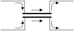
To counter this the solution I thought about is to put four connections on
the conducting straps:

The whole can too be rolled to become a cylinder. Yet this
time with two pairs of connections coming out of the cylinder:

This could be the schematic drawing for that condensator type:

Using this condensator shape the signal can be forced
to go through the entire condensator. The condensator acts
like a transmission line, yet wit an opposite purpose:
while a transmission line is designed to keep the signal
shape unchanged, the four-legged condensator is designed
to flatten the signal.

Tests with electrolytic condensators showed the attenuation for high
frequency perturbations was virtually perfect. They could not be measured at
the output. In one test, a standard two-legged big electrolytic
condensator was used to shortcut a TTL signal. Yet the rising and
falling edges of the TTL signal that came through still were powerful
enough to trigger the TTL input gate at the other side. Then the
condensator was opened and two more connections were soldered to the
conducting straps, to make a four-legged condensator out of the standard
condensator. This time, the TTL input received no more signal.
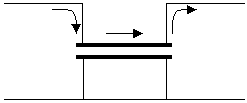
In some cases one of the two signal wires cannot be split. For example when it is a reference ground wire. In that case there is no choice but shortcut the wires of one of the straps. This reduces the yield of the condensator:

One solution is to put a lot of connections on the "ground" strap.
The best way to do this is probably for SMD components: The
"ground strap" can be also the case of the condensator,
intimately soldered to the ground wire. The signal would go
through two little connections entering the condensator,
insulated from the case.

Other condensator shapes can benefit too from this idea. For example
ceramic condensator made of a pile of a lot of little surfaces all
directly latched to one of the two connection wires. Or tantalum
sponge condensators. The point is the signal must be forced through
the plates or through the sponge.
